Process Flow Chart |
Дневник |
| What is a Process Flow Chart
A Process Flow Chart is a type of flowchart which is mostly used in industrial, chemical and process engineering for illustrating high-level processes, major plant processes and not shows minor details. A Process Flow Chart is often used:
A Process Flow Chart usually consists of:
ConceptDraw PRO diagramming and vector drawing software extended with Flowcharts Solution from the "What is a Diagram" Area of ConceptDraw Solution Park is the best way to create Process Flow Chart and other types of flowcharts.
Example 1. HR Management Process Flow Chart Benefits of Process Flow Chart The Process Flow Chart has a wide set of benefits:
ConceptDraw PRO software with Flowcharts Solution is the easiest way to create a new Process Flow Chart, Flow Process Chart, Flow Chart Process Map, or even High Level Process Flow Chart. We propose to start with a Basic Flowchart template available from ConceptDraw Solution Browser.
Example 2. Basic Flowchart Template Another way is to start with one of samples included in Flowcharts solution, choose that is closely resembles your project or create new document and work in it. Filling template, changing ready sample or designing a Process Flow Chart at new document, use the predesigned vector objects offered in Flowchart and Flowcharts Rapid Draw libraries of Flowcharts solution. Each of offered objects is ready-to-use, simply drag it from the library to your document and use according to your needs. In addition each object is vector, so you can easily resize it without loss of quality and change its color style.
Example 3. Process Flow Chart. Design Elements — Product Life Cycle The Flow Process Charts you see on this page were created in ConceptDraw PRO software using the tools of Flowcharts Solution. These samples are available for viewing and editing from ConceptDraw Solution Browser. Use the Flowcharts Solution for ConceptDraw Solution Park for fast and easy designing professional looking Process Flow Chart of any degree of complexity. All source documents are vector graphic documents. They are available for reviewing, modifying, or converting to a variety of formats (PDF file, MS PowerPoint, MS Visio XML, and many other graphic formats) from the ConceptDraw Solution Browser v3. The Flowcharts Solution is available for all ConceptDraw PRO v9.5 or later users. |
|
||
|
TEN RELATED HOW TO's: Interior Design Piping Plan - Design Elements Every apartment needs renovation from time to time, as some home systems such as wiring or plumbing may fall out. When developing the future design of a piping system, the engineer should take into account many aspects. Replacing the worn plumbing begins with the choice of materials and sizes of pipes for the new system. Each proposal has its own pros and cons that should be considered before purchasing. It is also relevant to draw attention to temperature changes that might effect pipes, such as freezing or thermal expansion. Let’s take a closer look at possible pipes materials. Recently, steel pipes were the most common, and now they can still be purchased. The most important advantage of steel is that it is eco-friendly and the fact that they have passed the test of time and pipes of good quality can function for more than 50 years. Remaining pros: high operating pressure and temperature, as well as small thermal expansion. The negative sides of steel pipes include their big we Read more... →  Picture: Interior Design Piping Plan - Design Elements Related Solution: Plumbing and Piping Plans Types of Flowcharts A Flowchart is a graphically representation of the process, algorithm or the step-by-step solution of the problem. There are ten types of Flowcharts. Using the Flowcharts solution from the What is a Diagram area of ConceptDraw Solution Park you can easy and quickly design the Flowchart of any of these types. Read more... →  Picture: Types of Flowcharts Related Solution: Flowcharts Pyramid Diagram A three level pyramid model of different types of Information Systems based on the type of decisions taken at different levels in the organization. Read more... →  Picture: Pyramid Diagram Related Solutions: Marketing Diagrams, Pyramid Diagrams How to Report Task's Execution with Gantt Chart ConceptDraw PROJECT’s powerful reporting engine lets you generate a set of tabular reports with just one click, or visualize your project as Radial Tasks Structures, Work Breakdown Structures and Resource Calendars. It also provides you with dynamic Project Dashboards. Read more... →  Picture: How to Report Task's Execution with Gantt Chart Processing Flow Chart Processing Flow Chart is a simplified sketch which is used in chemical and process engineering for illustrating general plant streams, major equipments and key control loops. ConceptDraw PRO enhanced with Flowcharts Solution from the "What is a Diagram" Area of ConceptDraw Solution Park is a powerful Processing Flow Chart software which will help save lots of your time. Read more... → Mathematics Solution from the Science and Education area of ConceptDraw Solution Park includes a few shape libraries of plane, solid geometric figures, trigonometrical functions and greek letters to help you create different professional looking mathematic illustrations for science and education. Read more... → |
|||
Метки: Process Flow Chart Process Flow Chart |
Process Maps |
Дневник |
Process Maps are detailed flow diagram of the process using color coded symbols that drill further into the high level map generated on the SIPOC.
The purpose is to visually represent the process as it is in reality. Complete the current state map by walking (GEMBA walk) and experiencing the process. This is a valuable learning experience, the team will quickly gain insight about the actual flow. Don’t sit in a room and think it through yourself or with the team. Patience, time, asking questions are all part of the completing this map.
Create a current state and a future state. Your team may want a future state with a short term target (such as 90 days) and a long term ideal state.
Objective:
To capture all the complexity and improvement opportunities by analyzing each step in detail. Seek out the 7-Wastes and enhance current value-added activities.
Look for:
These represent opportunity for waste elimination. Proceed with the goal to eliminate waste before settling for waste reduction. Throughout the entire process map, look for the 7-Wastes. So, before process mapping, educate the team on how to "see" waste.
Take caution when considering "automation" to take over manual processes. People are adaptable and much more flexible. Automation is fixed, constant, and often difficult to fix and maintain. In a JIT environment the decision to automate is advised with caution.
This map is considered a living document. It is meant to be reviewed and updated on a continuous basis. The more detail it contains, the better understanding you and the team will have of the true process and opportunities.
A good process map gets the process from the 50,000 foot level to the ground level of the actual process.
The development of the map is a team effort and it will educate everyone on the reality of the process and most often how little of the total process is value added. Typically, there are obvious improvements that will be become evident while the mapping is being done.
It will not be perfect the first time through, add more detail as it evolves. It is important to remain with the Start and Finish boundaries set forth by the SIPOC in the DEFINE phase.
The team needs to begin identifying the value added steps versus the non-value added steps and time. This realization is clearer during Value Stream Mapping (VSM) that adds more quantification to the steps.
Creating a future state or ideal state (while being realistic yet not too limited) will make it clear to the team that everything getting in the way is opportunity to improve. Laws, regulations, customer standards, past paradigms all need to be challenged because they change over time.
Creating a process map on a computer is common and many software programs exist that have symbols created. However, the first drafts are often very complex and frequently revised.
Create the real flow on paper and post it publicly for others to offer input and critique. It is very important to catch the rework loops, communication issues, decision delays, stops, starts, pick-ups, drop-offs, and other waste so the team fully understands the opportunities.
These hidden factory "what-if" and "sometimes" paths are important for everyone to document and understand. This knowledge will create better subjective decisions when assigning weights to the inputs using the subjective root cause analysis tools in theMeasure phase.
Rework loops are where defects and wasted time are occurring. The team should focus on preventing them, reducing their severity, and detecting them if they can not be eliminated.
Some product or process may actually go through the rework path multiple times and the map does not illustrate this unless specially noted and discussed.
The picture below shows two Rework Loops. Rework loops have varying severity. The process map does not show the amount or cost of pieces scrapped or the amount or cost of pieces reworked. Use the yield calculations to get this data.
Often a Rolled Throughput Yield (RTY) is calculated to help quantify the scrap and rework through these loops and this does not always mean the lowest RTY is the worst financially or to the customer.
If one type of rework is more expensive or higher risk to the customer (such as a delayed delivery), then it may be a higher priority to improve. This is all going to shake out in the subjective root cause analysis tools and the inputs get funneled out to the most important, key process input variables (KPIV's).
Insurance companies will often use flowcharts to identify hazards or perils that could result in exposure. Flowcharts should also be used by the team to evaluate ideas to reduce these exposures, similar to reducing the severity, occurrence, and detection of an input within aFMEA.
Risk managers often use them along with questionnaires for employees, inspections, and statistical analysis of previous losses to establish premiums for the company. Have an internal Risk Manager sit on your team from your company may be another way to capturefinancial savings.
Through a careful and detailed inspection process the best overall risk assessment can be done. Process Maps can provide a lot of information in an easy to read format. They will be looking for potential problems that are a combination of hazards, perils, and exposures.
For example:
A Six Sigma team may be working to reduce the number of Recordable Injuries and Lost Time Injuries. Some improvements that may be implemented are alarm systems, sprinklers in new areas, facility-wide intercoms, and others that may also qualify your company for reduced property insurance premiums.
|
|
|
Theoretically, the perfect state of a value stream or flowchart is to have 100% of the steps adding value.
What does this mean?
Value-Added:
There is some debate about compliance steps. Certain steps are done to meet compliance criteria such testing and documentation. There is usually opportunity to streamline this "regulatory" or "business-mandated" processes.
The team should review these and not simply accept that they are requirements. Challenge the process and rule, ensure that the rules have not changed and get evidence of the rule to validate. Perhaps, the current method has waste or even the requirement is not being met.
Non-Value-Added:
|
This module provides lessons on how to use different types of process mapping tools to breakdown and understand your business processes. It also gives an insight of how the outputs from this tool can become critical inputs for the more advanced tools you may use through your DMAIC journey.
|
Different sources will use suggest different colors denotations for symbols. The color will help to identify specific steps when looking at very detailed maps. It is important that your teams uses a consistent color scheme. There are hundreds of symbols, some of the most common are shown.
Several other visual tools are forms of Process Maps and each has a specific use, is a part of another tool, or is a type of process map.
For example, the SIPOC is more than a very high level process map, it defines the Suppliers, Inputs, Outputs, and Customers and its "Process Map" portion is very generic.
Some of these tools are:
-IDEF Modeling
-SIPOC (very high level)
-Deployment Flow Chart - (focuses on hand-off points)
-Value Stream Map (more quantitative but also has limitations)
-Activity Diagram (more detailed than the SIPOC)
-Detailed Process Map (most detailed "ground" level)
-Swim Lane Process Map
Review the SIPOC module
Return to the DEFINE phase
Return to the MEASURE phase
Search active job openings related to Six Sigma
Return to the Six-Sigma-Material Home Page
Метки: Process Maps |
Process Map Example |
Дневник |
Метки: Process Map Example |
How to Create a Flowchart |
Дневник |
Four Methods:Design the ConceptCreate a Flowchart in ExcelCreate a Flowchart in WordFlow Chart HelpCommunity Q&A
Flowcharts are a great tool for breaking down difficult to understand processes into accessible concepts. Creating a successful flowchart means balancing the information you need to convey and the simplicity with which you present it. Follow this guide to make flowcharts in Excel and Word.
Method1
Design the Concept

1
Write out your core concepts. The key to a successful flowchart is its readability. Make sure that your core concepts are simply stated, and that the progression from concept to concept is explained in simple steps.
2
Decide between a standard or swimlane format. A standard flowchart breaks a process down by its key concepts and required actions. If you have multiple groups involved in the process outlined by the flowchart, a swimlane format can help show who needs to do what. Each flowchart step is placed in the “Lane” for the group responsible for completing the task (Marketing, Sales, HR, etc.).3
Layout your flowchart. Before you start designing your flowchart through software, draw it out on a scratch piece of paper. Place your starting concept at the top, and expand the chart out below it.
4
Separate complex processes. If areas of your flowchart are becoming too dense, separate the subprocess into a new flowchart. Add a box as a reference to the subprocess in the original flowchart, and have the reader return to it when they get through the expanded section.
Method2
Create a Flowchart in Excel

1
Create a grid. Excel spreadsheets are formatted by default to have cells that are wider than they are tall. To create a uniform flowchart, you will want to set the cell sizes to be square. To do this, click the Select All Cells button located in the top-left corner of the spreadsheet.
2
Set your margins. If you plan on exporting the spreadsheet to Word or another program, you will want to make sure that the margins line up. Use the Margins menu in the Page Layout or Layout tab to adjust the margins to match the software you are exporting to.
3
Create shapes. Click the Insert tab and select the Shapes menu. Select the shape that you want to create and then draw the size of the box using your mouse. Once you create a shape, you can change the color and outline style using the tools in the Format tab that opens.

4
Add text. To add text to shapes, click on the center of the shape and start typing. You can adjust the font and style in the Home tab. Keep your text short and to the point, and ensure that it is easily readable.

5
Connect the shapes. Open the Shapes menu from the Insert tab. Select the line style that most suits your needs. Hover your mouse over the first shape. You will see small red boxes appear on its edges that show where lines can be connected.
6
Download a template. Instead of creating a flowchart from scratch, there are a variety of Excel templates and wizards available both for free or for purchase online. Many of these take most of the work out of creating a flowchart.
Method3
Create a Flowchart in Word

1
Insert a canvas. The easiest way to create a flowchart in Word is to first create a canvas. A canvas allows more freedom to work with shapes, and enables some features that aren’t normally available, such as connecting lines.
2
Enable the grid. Using a grid will allow you to create uniform shapes. To enable it, click on the canvas to make it active. In the Format tab, click Align and then select Grid Settings. Check the boxes for displaying gridlines and snapping objects.

3
Create shapes. With the canvas active, select the Insert tab and click the Shapes menu. Select the shape you would like to add. Use your mouse to draw the shape to the size you would like. Once you create a shape, you can change the color and outline style using the tools in the Format tab that opens.

4
Add text. To add text to a shape in Word 2007, right-click on it and select Add Text from the menu. For Word 2010/2013, simply click the shape and start typing. You can adjust the font and style from the Home tab.

5
Connect the shapes. Open the Shapes menu from the Insert tab. Select the line style that most suits your needs. Hover your mouse over the first shape. You will see small boxes appear on its edges that show where lines can be connected.


Метки: How to Create a Flowchart How to Create Flowchart |
Five Tips for Better Flowcharts |
Дневник |
When designing and creating a flowchart, bear in mind that the diagram needs to be easy to understand. Here are five tips for good flowchart design. Applying them will allow you to make flowcharts that are easier to read, understand, and use.
1. Use Consistent Design Elements
Shapes, lines and texts within a flowchart diagram should be consistent.
This example shows how consistency is applied. Notice how only the start and end shapes are oval. All the others are rectangles. Every shape is the same size as is the spacing between them. They also have the same outlines and are aligned uniformly.
Using consistency eliminates unnecessary distraction and makes the data flow or workflow very easy to follow.
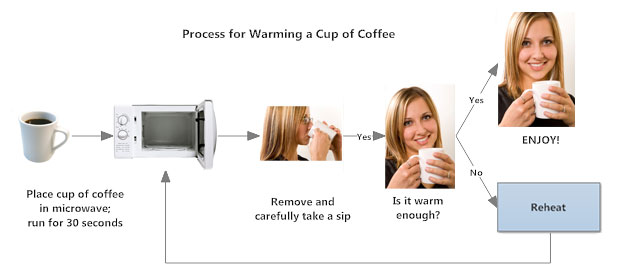
Sometimes color is helpful in making process steps clearer. Certain types of processes, such as decisions, might be shown in a different color, as might steps that require the user to return to an earlier step (such as 'Reheat' in this example.) Spacing, on the other hand, should always be consistent. Most drawing programs require you to do this manually, which can be time-consuming, so if you're looking at software, be sure to look for something with automated drawing and formatting built in.
There may be times when it is acceptable, and perhaps even preferable, to draw a flowchart that moves beyond a basic, simple design scheme. Making a flowchart with photographs might be one of those situations. This can make a flowchart a more interesting element in a presentation slideshow, for example. It also might be useful in the event your audience is multi-lingual. Maybe there are steps in the process that are more clearly explained with a picture. A good software program will let you make flowcharts with photos, symbols, hyperlinks, and so forth.
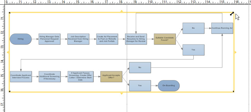
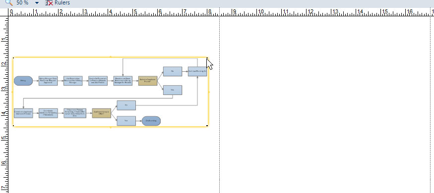
2. Keep Everything on One Page
It is good practice to make sure that the flowchart fits on a single page and the text remains readable. When a diagram becomes too large to fit on a page, it's advisable to divide it into multiple charts and connect them with hyperlinks.
To keep your flowchart to one page you can try a few solutions outlined below:
A. If it's just slightly too big, try scaling it down. Remember, though, that the font you're using will also scale. For example, if you're using 10-point font and scale the diagram to 60% its original size, your font is now effectively 6 point. A tip here is to use a larger font that will offset the reduction in scale. In this example, if you re-set your font to 16 point then a 60% scale will result in 9.6-point type. Of course, using a larger font will probably increase the sizes of the symbols, so you may need to make a few adjustments to get the right look.
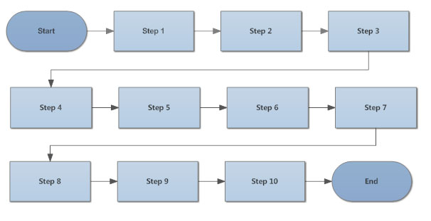
B. Depending on the number of steps, you can also have your chart flow left to right, then down to a subsequent line where it continues. It will look something like this:
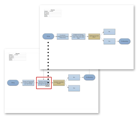
C. Another way to handle a large flowchart is to break it up into a collection of smaller ones. Do this by starting with a top-level diagram that provides a brief summary of the steps in the complete process. Each of these brief summaries will then contain a hyperlink to a separate flowchart that shows the details of that step. The steps in the detail flowcharts may themselves be summaries of even more detailed steps, or sub-processes. These will, in turn, be hyperlinked in the same manner. This may continue into several layers of detail.
3. Flow Data from Left to Right
Structuring a flowchart from left to right makes the information easier to read and comprehend.
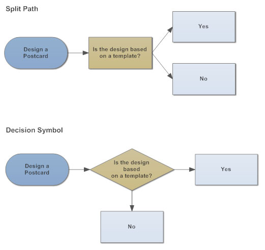
4. Use a Split Path Instead of a Traditional Decision Symbol
Traditional flowcharts use a diamond symbol to represent a decision. There are three inherent problems with this:
The use of a split-path eliminates all three. It continues the left-to-right process flow, and it's easy to see and understand without explanation. Here's an example showing the same process using a split-path versus a traditional decision symbol:
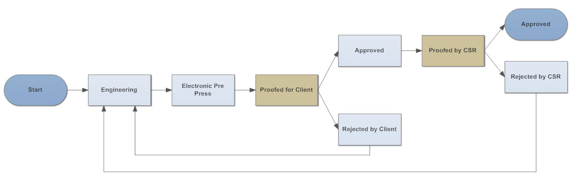
5. Place Return Lines Under the Flow Diagram
Since we naturally read text from the top of the page down, it is logical that return lines should be placed under the flowchart rather than above. If two return lines are needed, they shouldn't overlap. Here's an example of how return lines should look:
Examples of Good Flowchart Design in Practice
In today's world, flowcharts are often used for improving business processes. When applied in this area, they are also sometimes referred to as business process maps, workflow diagrams or just simply process maps.
But let's not get too hung up on terminology. For most users, the goal of diagramming business process flow is to improve organizational efficiency. It might start with an "as is" analysis that looks at current workflow with an eye to finding areas for improvement. Another use would be to document a process for regulatory compliance or to ensure quality control, such as an ISO 9000 or ISO 9001 quality management system. Flowcharting a business process can also be beneficial in training new employees.
However, an inherent problem has emerged. That problem is that traditional flowcharts are frequently created in such a way that they aren't easy to understand, because they don't follow our five tips for good flowchart design.
Let's look at a few flowchart examples that can be improved by applying these design tips.
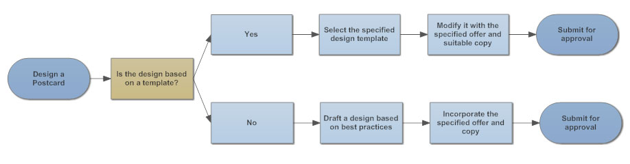
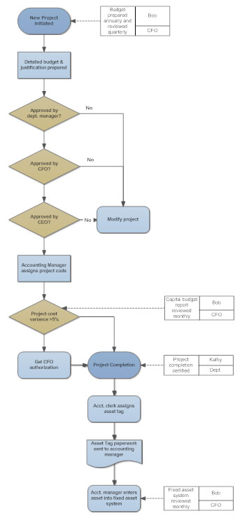
This diagram is designed with a top-down orientation. It uses traditional symbols such as decision diamonds and a document shape.
One of the problems that can be encountered using traditional flowchart designs is that they can be difficult to both create and use in a simple, understandable manner. For example, note that the "modify project" box has no outlet,thus the user faces a dead end at this point.
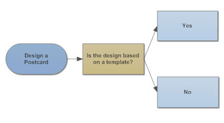
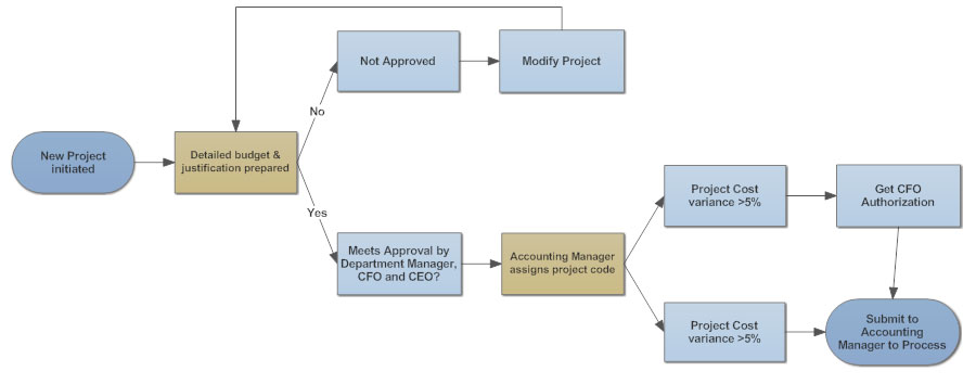
Here's a redesign of this flowchart. It follows a more readable left-to-right flow. Rather than diamond-shaped decision boxes, it employs a split path. Notice how the "modify project" box now has a return arrow that directs the user back to a previous step in the workflow process.
The other notable difference in this example is that there are only two shapes: ovals for start and end of the process and rectangles for everything else. This format doesn't require any deciphering on the part of a user.
Purchase Order Approval Process Flowchart
Take a look at the following flowchart. Do you see any potential problems in trying to follow the workflow process outlined here?
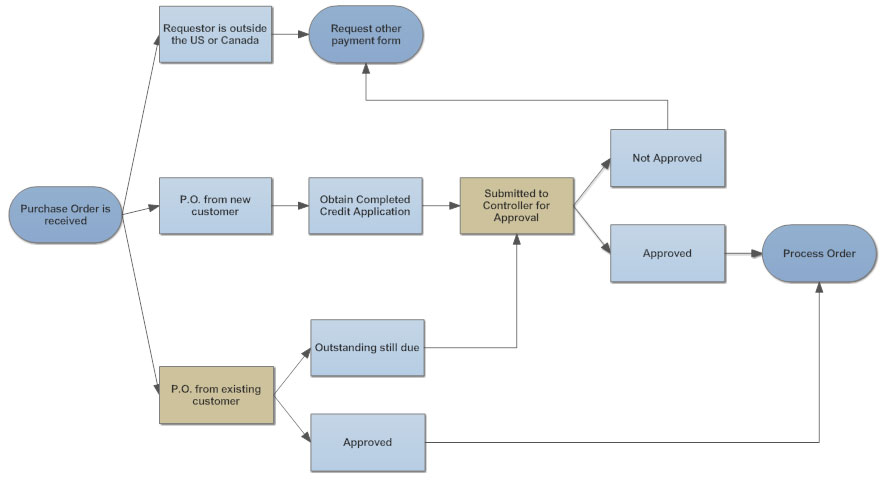
Here are just a few of the issues that might arise when trying to follow the process as diagrammed.
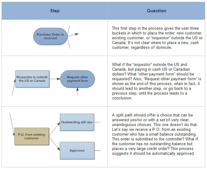
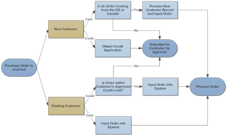
Let's look at the same flowchart, revised to make it easier to understand and use.
When the order is received, it is simply processed into two buckets: new versus existing customers. The next steps for orders from existing customers are very simple: if they are paying cash, their order is logged and processed. Credit orders within the customer's credit authorization are also processed immediately. Otherwise, they are routed to the controller.
New customers placing credit orders simply require an application and are routed to the controller; regardless of their location. Cash customers in the US and Canada are processed at this level, but foreign customers must be routed to the controller's office for approval.
This flowchart is easy to follow and understand, even for a new hire. There are only two terminations: either the order is approved at this level and sent to processing or it is routed to the controller's office. You'll note that this process is not concerned with what happens at the controller's level. That would be done in a separate chart.
The key to a good business process map, as this example shows, is that it has a logical start and end and that the steps in between are easy to understand and follow.
Always remember that the priority is to make your flowchart diagram easy for the user to understand. Applying these basic design tips will help you meet that goal.
A good flowchart software program will have automatic drawing features that let you create this type of diagram effortlessly.
https://www.smartdraw.com/flowchart/flowchart-tips.htm
Метки: Tips for Better Flowcharts Tips Better Flowcharts Flowcharts |
Flowchart Benefits |
Дневник |
1. Visual Clarity
One of the biggest benefits of a flowchart is the tool's ability to visualize multiple progresses and their sequence into a single document. Stakeholders throughout an organization can easily understand the workflow while finding out which step is unnecessary and which progress should be improved.
2. Instant Communication
Teams can use flowcharts to replace meetings. Simply clarifying progresses offers an easy, visual method to help team members instantly understand what they should do step by step.
3. Effective Coordination
For project managers and resource schedulers, the benefits of a flowchart include the ability to sequence events and reduce the potential for overburdening team members. Eliminating the unnecessary steps help to save time and resources.
4. Efficiency Increase
Efficiency increases are a significant benefit of flowcharts. The flowchart lists each step necessary to perform a process. The flowchart helps a designer remove unnecessary steps in a process, as well as errors. The flowchart should only include the steps that are requirements to reach the endpoint of the process.
5. Effective Analysis
With the help of flowchart, problem can be analyzed in more effective way. It specifically shows what type of action each step in a process requires. Generally, a rectangle with rounded edges defines the beginning or end of the process, a diamond shape shows the point at which a decision is required, and a square block shows an action taken during the process. A flowchart may also include symbols that show the type of media in which data is stored, such as a rectangle with a curved bottom to show a paper document or a cylinder to symbolize a computer hard drive.
6. Problem Solving
Flowcharts break a problem up into easily definable parts. The defined process displayed by the flowchart demonstrates the method of solving a complex problem. A flowchart reduces the chance that a necessary step for solving a problem will be left out because it appears obvious. In this way, it reduces cost and wastage of time.
7. Proper Documentation
Digital flowcharts serve as a good paperless documentation, which is needed for various purposes, making things more efficient.
https://www.edrawsoft.com/flowchart-benefits.php
Метки: Flowchart Benefits Flowchart Benefits |
How to Document a Process |
Дневник |
Companies often document a process to make sure each worker knows how to perform it correctly, or to analyze a process for improvement. If you are asked to document a process, or decide to do it yourself, make sure you involve people who are experienced and knowledgeable about the process as a whole. Two types of flowcharts are described below, but if you think a different type of simple diagram or a text document is more suitable to your process, you may use that instead. In that case, read the general advice section to get an idea of the purpose of process documentation.
Method1
Deciding How to Document Your Process

1
Stick to one process at a time whenever possible. Don't try to describe your entire job in one flowchart. A series of short documents that cover each task separately will be much easier to follow.

2
Break down the big picture into sub-processes. Sub-processes are the key tasks that are performed during the process. If you are not intimately familiar with the process you are documenting, interview project managers or other experts in this process to get a good understanding of the tasks involved.

3
Decide whether the process is simple enough for a text document. If your process is similar every time, and involves only a couple of decisions or variations, you might want to simply write out the steps in a list. Use an electronic text document (such as a Microsoft Word file) or a sheet of lined paper.

4
Consider making a flowchart. A simple flowchart is an easy way to display the process visually, as described in a later section on this page. There are ways to construct more complicated flowcharts as well, but these are not required for most processes. Consider following the instructions in the section on complex flowcharts only if your process has more than ten steps and you have more than three people performing different steps of the process.

5
Keep it short when possible. One page is ideal, but even for complicated processes, try to pare it down to 5 pages or fewer. Only specialized and complex tasks should require longer documents, and even then only if the document is being used by the actual people performing them.

6
Include visuals if they help make the process easier to read. Some people understand visual representations better than reading text, especially if they are executives, managers, or other people who may not have hands-on experience in the process you are documenting. These can be diagrams, photographs, or screenshots, but keep them simple and clear.

7
Refer to people by title, not name. The document may outlast an individual. Don't write "Send meeting minutes to Carol." Write "Send meeting minutes to the chairman."[1] If you think the name is necessary so readers know who to contact, include both the name and the job title.

8
Make it clear how processes connect to each other. For example, a process document for "Arranging the Newsletter" might end with a note "The end result is sent to editing. See the document titled Editing the Newsletter." The document titled Editing the Newsletter may begin with the note "This is preceded by Arranging the Newsletter." and end with "This is now sent to publication. See the document titled Publishing the Newsletter."

9
Make documents editable and accessible. Make copies available for people to read or study. Keep an electronic master document in an editable format so changes can be made if necessary.[2]

10
Label process documents carefully. Write the date created and the date last edited in an obvious location on each document, such as the top of the page. If multiple people are editing the document, you may wish to put your name or initials next to the last edited date. Finally, include a title and file name that clearly communicates which process is documented.
Method2
Creating a Flowchart

1
Create a flowchart to easily explain simple tasks. Flowcharts are great for depicting basic information in an easy to read, visual style. They can be used to guide new workers through simple tasks during job training, or to assist a worker who is performing a task temporarily due to a coworker's absence.

2
Arrange the flowchart from left to right, or from top to bottom. When making a flowchart, you'll write a box for each task within the process, and connect them with arrows to show which order you perform these tasks. Start at the left-hand side or the top of the page, just as you would when writing. Sequencing the steps in this order makes it easy to tell at a glance which to follow.

3
Begin with a circle labeled "start." If your flowchart is small enough to fit in one row or column, you may not need this circle. For more complicated flowcharts, having an obvious circle labeled "start" is useful.

4
Draw a rectangle with the name of the first task written inside it. Draw an arrow pointing from the "start" circle to a box with the first task inside it. For instance, "take customer's order."

5
Draw an arrow to the next task or question. This arrow points to the next box, with the second task written inside it. If there is a decision to make or a question to answer before the second task can be performed, write the question inside a diamond instead.

6
Lead from decision diamonds to tasks depending on answer. For example, say the box with the task "Take customer's order" leads to a diamond, with the question "was water ordered?" Draw two arrows leaving the diamond. On one arrow, write "yes" or "y" and lead to a box labeled "give customer water." On the second arrow, write "no" or "n" and lead to a box labeled "give order to cook."
Method3
Creating a Complex Flowchart

1
Use this for complex processes that involve multiple people or departments. If you are documenting a complicated process that involves several people, teams, or departments working independent, consider making a complex flowchart. The type of flowchart described here is called a "swim lane chart" or "Rummler-Brache chart."[3] The chart makes it easy to see who is responsible for each task, and helps identify areas where the process could be improved.

2
Consider using software. The flowchart will probably end up looking tidier and more readable if you use software for creating diagrams. Having an electronic file also makes it easier to make changes to the flowchart as needed. Search online for "process mapping software," making sure to download or purchase one that can create Rummler-Brache charts.

3
List each participant in a neat column on the left side of page. Each row can be labeled with a department, team, or the job title of individual. Each participant is responsible for tasks located in his horizontal row, extending across the page. This is sometimes called that participant's "swim lane."

4
Start with the first task. Begin the process by placing the first task in a box near the left hand side of the page, just to the right of the participant responsible for that task. For example, if the Research division starts the process by creating a product idea, draw a box just to the right of the word "Research" and label it Create product idea.

5
Continue as you would a normal flowchart, but keep tasks moving to the right and placed in the appropriate row. For example, if Research then sends its product idea to Marketing for focus testing, draw an arrow from Create product idea to a box in the Marketing row, to the right of the previous box. Label this box Focus testing.

6
Learn how to use diamonds and circles. Most flow charts use boxes, diamonds, and circles, plus arrows between them. You've already encountered the box, which is labeled with the name of a task. Use a diamond when there are multiple possible results. Use circles when an end result has been achieved. Continuing the above example, draw an arrow fromFocus testing to a diamond labeled Is product approved? Draw one arrow from the diamond, labeling it no, and connect it to a circle labeled End of process. A second arrow, labeled yes can lead to the next task in the process.

7
Stay consistent. Use similar sized boxes and no more than two or three easily distinguished colors, to make the flowchart as readable as possible. For instance, all boxes (tasks) can have blue backgrounds, while all the diamonds (questions) can be yellow.

8
If necessary, move to another page. It's better to use multiple pages than to make the flowchart too small to read. Use clearly labeled tabs or arrows to make it clear how the flowchart continues. For instance, draw an arrow labeled A leading off the right-hand side of the page. On the next page, draw an arrow leading from the left-hand side of the page, also labeled A.

9
Edit the flowchart. Follow each possible "route" through the flowchart and see if it makes sense. Ideally, have someone else familiar with the process go through it with you to catch mistakes and identify missing steps. Once you have looked over it at least once and corrected any mistakes, the document is ready to present or send to other people involved. However, feel free to edit this flowchart if the process changes at a later date, sending the updated document to the people who use it.
Method4
Analyzing a Process Document to Improve the Process

1
Identify areas where quality overview might be useful. Each time the process moves from one person or team to another, consider whether someone should examine the work in progress to see if it is ready to continue. Is quality often sub-par after a specific step, such as a step usually performed by an inexperienced team member? Which processes have the highest overall effect on quality, and might need extra attention?

2
Look for duplicate tasks. If your diagram or document contains two identical tasks, consider whether this is useful or inefficient. Sometimes, it's good to repeat a task for better quality control (for instance, two departments inspecting a product at different stages). However, simple tasks such as proofreading shouldn't occur more than once in the process. Suggest that one of the duplicate steps be removed from the process procedure.

3
Look for unnecessary movement between departments. Your document might show that person A and person B transfers responsibility for the process back and forth several times. Is it possible to reduce the amount of unnecessary transfers? If you can reorganize the process, person A might be able to do several tasks in one period, then hand it to person B.
Метки: How to Document a Process |
Computer Help & Solutions : How to Create a Process Flowchart |
Дневник |
Метки: Computer Help & Solutions How to Create Process Flowchart |
Ultimate Flowchart Guide ( Complete Flowchart Tutorial with Examples ) |
Дневник |
Flowcharts were introduced by Frank Gilberth in 1921, and they were called “Process Flow Charts” at the beginning . Allan H. Mogensen is credited with training business people on the use of Flowcharts. Wikipedia has a great summary about the history of flowcharts, read more in this wiki section.

Flowchart Symbols
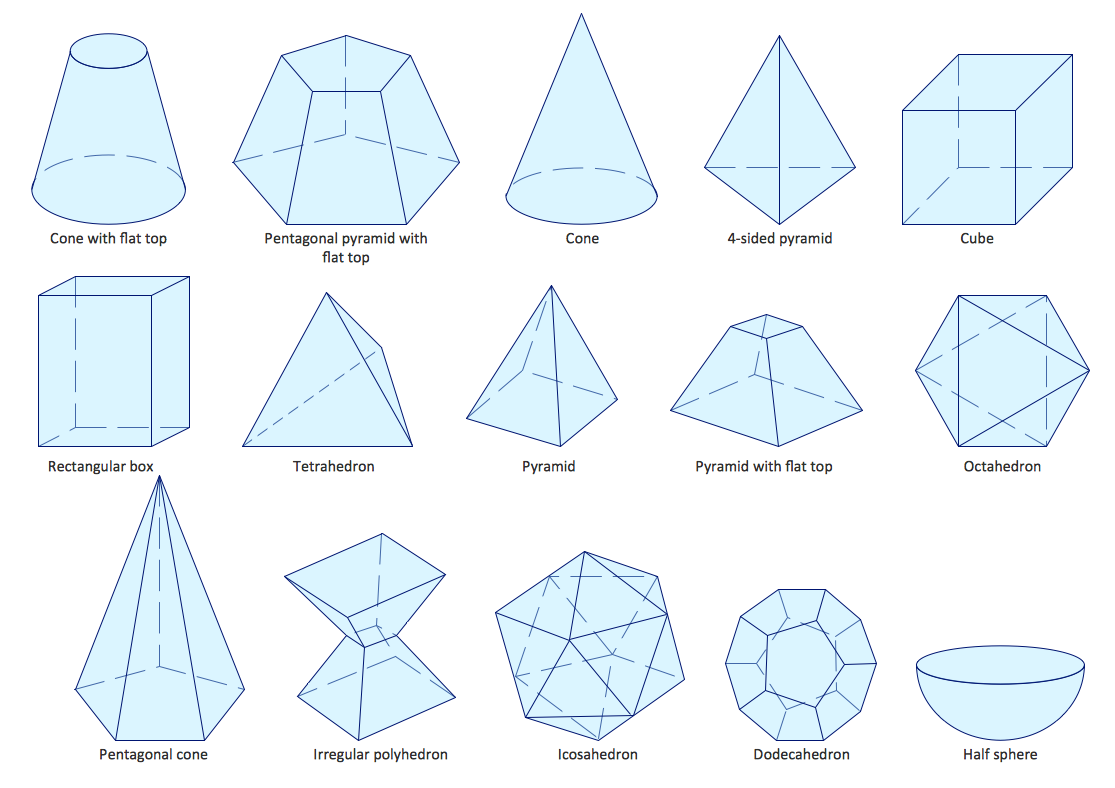
Before drawing flowcharts you need to understand the different symbols used in Flowcharts. Most people are aware of basic symbols like processes and decision blocks. But there are many more symbols to make your flowchart more meaningful. Below image shows all the standard flowchart symbols.
Most people don’t know about some rarely used flowchart symbols like Sequential access storage, Direct data, Manual Input etc. Check the flowchart symbols page for a detailed explanation of different symbols. Although these are the standard symbols available in most flowchart software, some people do use different shapes for different meanings. The most common example of this is the using circles to denote start and end. The examples in this flowchart guide will stick with the standard symbols.
Flowcharts can be categorized into four main types. Document flowchart, System flowchart, data flowchart and program flowchart. Not everyone agrees with this categorization, but the core principals of drawing a flowchart remains the same. You need to consider few things when drawing a flowchart, Check out 6 useful tips on drawing flowcharts before you start.
If you are drawing a flowchart with many responsible parties you can group them together using swim lanes. Swim lanes are a powerful technique to increase the readability of you flowchart so you should use them according to the situation. Read using swim lanes in flowcharts to learn more about the process.
Below video shows how to draw a flowchart using Creately. It is very simple to use and one click create and connect helps you draw them faster as well. You can drag and drop symbols from the library or drag images to your diagram by doing an image search.
Although you can start drawing flowcharts by scratch it is much easier to use templates. They help you reduce errors and reminds you about the best practices to follow. If you want to use a ready made template, go to flowchart templates page and click on the flowchart that best suits you. Click on the use at template after the image and you are ready to draw your flowchart. Below are two templates out of hundreds of flowchart templates available to the user. Click on any of them to start drawing flowcharts immediately.

Support Process Flowchart Template

Support Process Flowchart Template
There are few things you can do to make your flowchart universally accepted. And there are some things that you can do to make it visually pleasing to others as well. Using standard symbols will make it understandable for a wide audience. However it is important to remember that the idea is to give out information in a easy to understand manner. It is perfectly acceptable to use an alternative image instead of the document symbol as long as the audience understands it. Keeping the arrow flow to one side, using same size symbols, naming the decision blocks, processes, arrows etc are few things you can do to make it better. The common mistakes section covers most of these practices in detail.
This section highlights the common mistakes made when drawing flowcharts. Some of the things mentioned here are for better looking and more understandable flowcharts, not having them in your flowchart wont make it wrong. Since there are two posts covering these mistakes in depth I will link to them from this flowchart guide.
15 mistakes you would unintentionally make with flowcharts ( Part 1 )
15 mistakes you would unintentionally make with flowcharts ( Part 2 )
A flowchart guide isn’t complete without some case studies.Below are three case studies and real life examples on how flowcharts can help you make decisions.
I hope this flowchart guide will help you to come up with awesome flowcharts. Flowcharts are a great way present complex processes in a simple to understand manner and they are used all over the world in many industries. If you have a question about drawing flowcharts or have any suggestions to improve this post, feel free to mention in the comments section.
http://creately.com/blog/diagrams/flowchart-guide-flowchart-tutorial/
Метки: Flowchart Guide |
| Страницы: | [1] |